
Description
The SSL 2611 V-Gates 2.0 is an updated version of our popular 2610 with improved circuitry, simple panel graphics and only 8 HP width. It sports a powerful combination of features for your clocking and gating pleasure. In fact, there are well over 300 variations of gates, functions and modes. And many of these functions can be voltage controlled!
Analog Knobs on a Digital Gate?
Absolutely! You bet! Although knobs might seem to make more sense for analog, with digital functions the knobs actually allow very versatile selections of what we call “Sub-Functions”. These sub-functions allow you to adjust how the gate outputs react with the input clock, among other things.
Modes, Functions and Sub-Functions
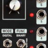
The 2611 has two Modes – analog & digital – each with three Functions. Functions (and sub-functions) allow control over how the outputs respond to the input. Sub-functions in digital mode, allow the outputs to selectively follow the input pulse width and control up/down actions.
Sub-functions in analog mode, controls the number of outputs affected by the input CV. In Analog mode, the 2611 follows an input control voltage (CV) to produce unique combinations of output gate signals. Binary, Step and Slope functions are available. A clock output is available that produces a 1 millisecond (ms) pulse for each change of output state.
In Digital mode, the outputs change in step with the input clock. Binary, Step and Random functions are available. This makes the 2610 very useful in creating rhythmic patterns, as well as random (no patterns) outputs. The outputs respond from DC to about 400 Hz.
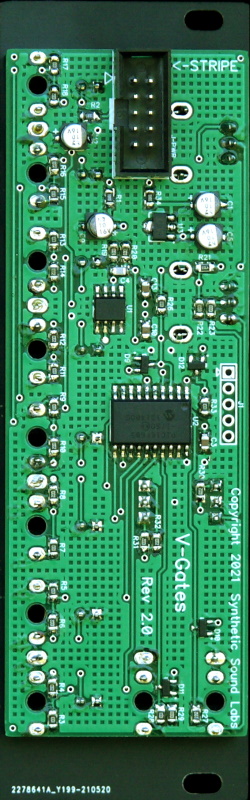
Diffused red LEDs display the output states. The Initial and external CV input controls respond linearly. Knobs are conveniently placed to allow ample room for manual adjustment. Top quality 1/8” jacks permit smooth, effortless patching. Quality, solder masked, fiberglass-epoxy printed circuit boards with precision computer controlled part placement and meticulous hand-crafted assembly assure years of trouble-free service.
So ask us what’s happening, and we’ll tell you “V-Gates”.
Reviews
There are no reviews yet