Description
Creative synth genius Ian Fritz has once again teamed up with Synthetic Sound Labs to bring you a totally new way to modify, modulate and crush your waveforms.
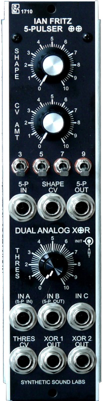
5-PULSER Section
The most effective waveshapers are the radical ones that produce multiple peaks per input wave cycle. There have been a number of these designed over the years, but most are fairly complicated circuits.
The SSL “5-PULSER” is a cost-effective waveshaper that produces an output train of pulses whose number (and widths) may be continuously varied with an external control voltage.
The setting of the SHAPE control determines the unmodulated output wave train. Assuming a Saw waveform input, at the lowest SHAPE setting a single square wave is put out, whereas at the highest settings a train of 5 pulses spanning less that half of the total wave period is produced. A set of four switches allow the third, fifth, seventh and nineth pulses to be switched in or out of the output signal path. The SHAPE CV input and attenuator allow the pulse train to be modulated by an external CV.
The module is easy to use. The input signal may be any continuous waveform. An audio-frequency Saw wave is the most usual driver, but Tri, combined Saw-Tri, filtered Saw, etc. all give interesting results.
Any kind of signal may be used for the SHAPE CV modulation. Typically a Sin or Tri LFO signal would be used to give a continuous sweep of the output waveshape, but any waveform and frequency may be used. Signals from envelope generators may also be used. Different combinations of the four switches produce different timbres. For initial experimentation the user might want to start with all the switches either off (one pulse) or on (up to five pulses).
This unique waveshaper provides an enormous range of timbres. A sweep through the waveshapes sounds somewhat similar to a sweep produced by a highly resonant bandpass filter, since, at certain voltages, square wave signals at 1, 2, 3, 4, and 5 times the input frequency are produced:
Clip of sweep
A video including a slow sweep of the SHAPE CV is available online:
Video of 5-PULSER and ANALOG XOR module operation
In the following sound clip, the drone voice uses a continuously varying waveshape, and the other parts use an ADSR to sweep the timbre with different depths and initial waveforms.
Sound clip 1
To explore the idea of getting sounds with both animation and timbre modulation, I put together some patches using both (1) a pair of 5-Pulsers added together and (2) a second sawtooth VCO detuned from the one driving the pulsers. The second SAW was run through a phase shifter modulated by an LFO. A third FM’d VCO was added in some of the patches. Here’s an audio clip of some of the sounds I got.
Sound clip 2
Videos of drone sounds generated by the 5-Pulser, along with patch diagrams, are also online:
Drone 1
Drone 2
(Dual) ANALOG XOR Section
Since “XOR” is a digital logic function, an immediate question is what does “Analog XOR” even mean. For this module the answer is that it accepts two analog input signals and produces a digital signal output according to a rule similar to the rule for digital logic.
In digital logic, the XOR output is low when either (a) both inputs are low or (b) both are high. The output is high when one and only one of the inputs is high. Thinking of this in terms of the sum of the input signals, the output is low when the sum of the inputs is zero, the output is high when the sum of the inputs is one and the output goes low again when the sum of the inputs is two.
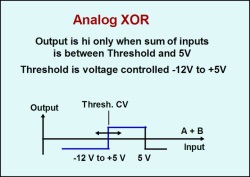
Along a similar line, the Analog XOR circuit outputs 5V when the sum of the input signals is within a certain voltage range, and -5V when the input sum is outside that range. The top of the range is fixed at a little over 5V, and the bottom of the range — referred to as the “threshold” — is adjustable. The THRES INIT panel control sets the threshold in a range of -12V (CCW rotation) to +5V (CW). The threshold may be modulated in the usual fashion using the THRESH CV jack and the THRESH AMT control.
An alternative way to think of the module’s operation is that it is a window comparator operating on the sum of the input signals. The limits of the window are the “threshold” voltage and ~5.5V.
Analog XOR module Operation
The Analog XOR module is a generalization of the very popular “digital ring modulator” (DRM) found in numerous analog synthesizers. In the traditional DRM, the input signals are “squared up” and then fed to a digital-logic XOR chip. So the output depends only on the signs of the input signals. The Analog XOR’s output depends on the actual analog voltage amplitudes of the input signals, as described above.
Operation is simple. For the first XOR, put any signals within +/-5V into the IN A and IN B inputs. Listen to the XOR 1 OUT output as the threshold is varied.
In the SSL module, two Analog XOR are employed. The first operates as described above. The second does too, except that one of its inputs is hard-wired to the output of the first XOR, ie, the two circuits are cascaded. Thus the cascaded combination has three independent inputs labeled as IN A, IN B, and IN C. The resulting cascaded sound is anharmonic in general and it can be quite harsh, but there are interesting tonal output signals when the three inputs are identical (or synced).
Note that the XOR inputs A and B are normaled to the 5-Pulser input and output, respectively. The normaled configuration is a good place for new users to start experimenting.
The video mentioned above has three examples using the Analog XOR circuits:
Video of 5-PULSER and ANALOG XOR module operation
The original thread on electro-music traces the development of the circuit, with lots of discussion by the DIY community and a number of audio clips.
Original thread


Reviews
There are no reviews yet